Act 1: Set-up
Hello World! We’re Shaun and Kelly and we want to know how things work. Whether it’s our rebuilt espresso robot (George Clooney) or our little satellites (Doves), we’re constantly inquiring into how things are designed and function. Lately we’ve both been particularly interested in motion – that little bit of wonder when the machine comes alive right before your eyes. That wonder is carefully designed by engineers and inventors like ourselves with particular constraints and requirements in mind. We found ourselves itching to better understand those design decisions that go into making things move!
Many people understand how to use an electric motor in their design yet few understand the trade space of motor design itself. As a pair of electrical and mechanical engineers, the electric motor covers the perfect combination of concepts based in both of our fields. We wanted to start at first principles and work our way through estimating datasheet torque values, allowing us to bridge the gap between the theoretical and the applied. Join us as we break something to find out how it really works.
Background
Physics Introduction: Calculating motor torque
We found two ways for calculating motor torque over the course of our investigation. The first is laid out in this paper from Rice.
The force on a conductor in a magnetic field is dependent upon the magnetic field strength  , the current flowing through the conductor
  , and the conductor length
  in the magnetic field.

If we fix our conductor around a rotating axis at a distance  from the center of rotation we can generate a torque
  due to the magnetic field.

For calculating maximum torque of the motor we assume that we’re generating a field that’s perpendicular to the magnetic field so  is set to zero.

The second approach is to use specific magnetic and electrical loading which is described in this book. These specific loadings are intrinsic to the design of the physical motor and allow us calculate torque from motor size.
The specific electrical loading  is the axial current () per meter of rotor under each pole, with a circumferential width of
  .
.

 is the specific magnetic loading, the rotor flux () averaged over the rotor surface area.

Using these two terms we can then calculate the motor torque by using the following equation, which multiples the specific loading values with the surface area of the rotor.

This means that we have two ways of reach our expected torque using measurements we can take from any motor which should be equivalent. We then decided to find a motor to tear down and calculate the expected torque.
Motor Introduction: AndyMark AM-0255 Motor
We wanted to find a powerful motor in the intersection of low cost and thoroughly documented. This lead us to the AndyMark AM-0255 2.5” CIM Motor – a mass production motor used heavily in the FIRST robotics competitions.
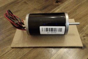
Andy Mark 2.5″ CIM Motor
This little motor runs about $30 and has, comparatively to other motors in that price range, extensive test documentation. So what’s the first thing we look at with a motor datasheet? The motor torque curve! It’s an interesting thing.
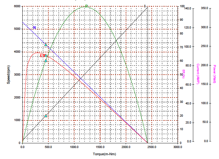
CIM Motor Test Curve
On this plot the speed torque curve represents the speed vs torque line. As torque is applied, the speed falls. As the torque increases, the current increases. The efficiency is the mechanical power output over the electrical power input (current2*R where R=0.091 Ohm).
Reading the plot at Torque = 0
At zero torque, we see the motor spins at 5,300 RPM and draws about three Amps. The motor produces zero power and thus the efficiency is also zero. This is called the No Load Speed.
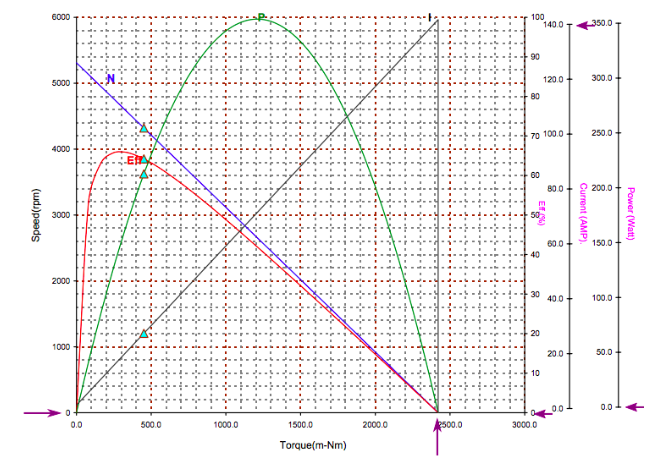
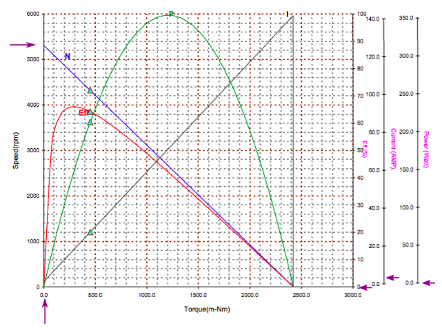
Reading the plot at Speed = 0.
At zero speed, we see the motor produces 2.4 Nm of torque and draws about 140 Amps. Since motor power output is the product of speed and torque, since the motor speed is zero, the output power is zero. Since again the motor is producing zero power and thus the efficiency is also zero. This is called the Stall Torque.
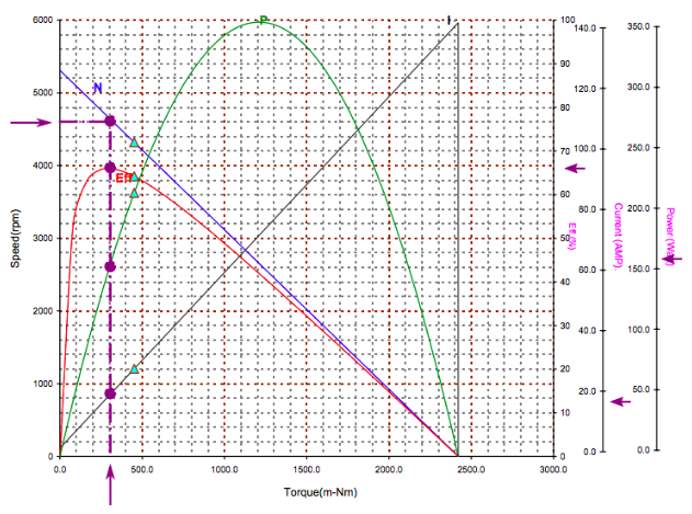
Reading the plot at peak efficiency.
By tracing the purple line, we see at peak efficiency, the motor spins at 4600 RPM under a load of 300 m-Nm. The motor produces ~160 W of power at 68% efficiency.
Using the motor theory above we should be able to calculate motor torque, within some error of the datasheet values, with nothing more than our motor’s physical and material properties.
Act 2: Confrontation
To measure certain properties of the motor we were going to have to take it apart. This motor only had 2 screws holding the stator between the brush plate and end plate, and it was simple to open up to gather the critical information we needed.
After opening the motor, we separated the rotor and stator from the brushes and end plates. Two permanent magnet poles are mounted on the stator and provide the source of the relatively constant magnetic field. Its rotor is made up of a slotted armature with 10 slots and 20 coils, lap wound. Each coil of 8 turns is wound around 4 teeth of the core, with two coils per winding in parallel. The start and end of each coil are each connected to two adjacent plates on the commutator.
On the brush plate there are two spring loaded brushes connected to the positive and negative lines on the motor. When the rotor is installed, the brushes each contact two adjacent commutator contacts on opposing sides.
On the end plate we found a funny manufacturing error. There was a tapped 4-bolt pattern in the end plate, usually used for mounting the motor externally. There was a second pair of holes around the same size, though un-tapped. These were intended for the bolts holding the motor together, but instead the bolts were using two from the other bolt pattern! Quality manufacturing right there.
We used calipers to measure critical values like rotor outer diameter, stator inner diameter, and pole lengths. These physical dimensions are critical to our calculations later. Our calipers gained an attraction to ferrous metals in the process – I guess it awoken something inside them.
| Measured Motor Parameters | Value | Units | |
| Number of Turns per Coil | 8 | turns | |
| Windings per Tooth | 16 | turns | |
| Number of Poles | 2 | poles | |
| Wire Diameter | 7.24E-04 | m | |
| Coils in Series | 5 | coils | |
| Coils in Parallel | 4 | coils | |
| Number of Slots | 4 | slots | |
| Coil Width | 3.70E-02 | m | |
| Coil Length | 5.80E-02 | m | |
| Tooth Width | 1.05E-02 | m | |
| Tooth Length | 4.40E-02 | m | |
| Pole Length | 5.68E-02 | m | |
| Rotor Outer Diameter | 0.04337 | m | |
| Stator Inner Diameter | 0.04483 | m | |
| Mass of Rotor | 4.53E+02 | g | |
| Mass of Armature | 3.33E+02 | g | |
| Mass of Copper | 1.11E+02 | g | |
| Distance Between Poles | 1.60E-02 | m | |
Then we put it partially back together sans stator, applied power, and played with it and a compass to show the directions of the fields generated.
We also hooked it up to a benchtop digital multimeter to measure the coil resistance.
It was time to break into the rotor further to see what more we could learn about the coils and windings. We wanted to confirm our assumptions about the number of turns and makeup of the rotor.

The rotor is made up of laminated magnetic steel plates that are mounted on a shaft. The steel plates make up the slotted armature, and each slot is insulated with a fibrous material [link to Aramid]. Then the coils of enamel-coated copper wire, 21 gauge, are wound around the teeth and through the slots. Then the whole rotor is dipped in epoxy… this was going to be a fun one to take apart. Cue the punch, the chisel and the heat gun.

The Punch – Not helpful
The Chisel – No Luck
The Heat Gun – Meh
Once removing a portion of the insulation material to expose the slots, we started unwinding the coils.


Like we expected, there were 8 turns per coil, two coils in parallel per contact. However, it did give us a better understanding of the lap winding and the order of the stacks. We labelled each slot with a letter and each contact on the commutator with a number and made the following table.

| Commutator Start | Commutator End | Start Slot | End Slot |
| 0 | 9 | B | H |
| 9 | 8 | A | G |
| 8 | 7 | J | F |
| 7 | 6 | I | E |
| 6 | 5 | H | D |
| 5 | 4 | G | C |
| 4 | 3 | F | B |
| 3 | 2 | E | A |
| 2 | 1 | D | J |
| 1 | 0 | C | I |
The result of this was we determined the armature was lap wound. We cleared out all the coils, and the armature was generally looking pretty messy, still covered in epoxy and mutilated insulation. Maybe we’ll want to rewind it someday? So we threw the armature in a tin can with some kerosene to see if we could strip off the leftover gunk more easily. It helped a bit.

So tearing this motor apart was not only fun, but also interesting. We got a better glimpse into its construction and confirmed our assumptions about the coils. We also learned a bunch more about lap winding after doing some more research, incited by this teardown.

Act 3: Resolution
So after all that what did we get?

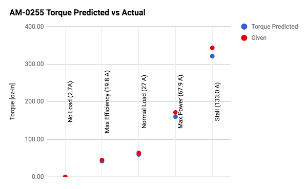
| Andy Mark Motor States | Torque Predicted | Given | Units | Error | |
| No Load (2.7A) | 0.00 | 0.00 | oz-in | – | |
| Max Efficiency (19.8 A) | 42.04 | 45.00 | oz-in | 6.58% | |
| Normal Load (27 A) | 59.74 | 64.00 | oz-in | 6.65% | |
| Max Power (67.9 A) | 160.30 | 171.70 | oz-in | 6.64% | |
| Stall (133.0 A) | 321.34 | 343.40 | oz-in | 6.42% | |
We expect our calculated values to be higher than the datasheet values because the system will have losses we can’t yet calculate in our spreadsheet. This includes things such as bearing imperfections, thermal effects, brush electrical and mechanical resistance, eddy currents, and air resistance within the motor housing just to name a few. Since our measurements are predicting a lower theoretical performance than measured, we are still missing something, however we feel the solution is within reach.
Here is our spreadsheet. It was the culmination of many hours of research, whiteboarding, and head scratching. During this process we worked both forward from theory and backward from the datasheet to help us fill in the gaps in our understanding.
Act 4: Epilogue
This exercise in reverse engineering this motor is just the beginning in our effort to better understand electric motors and making things move! We want to apply what we learned here to other DC motors, as well as explore other types of motors. We started testing another CIM motor for the Dodo Project to see if we can back out the test curves as they are not readily available. Eventually, we hope to dig deeper into the more subtle concepts of back-EMF and eddy current as they apply to electric motors. Along the way, we plan to build some cool stuff using these motors!
Future Experimental Set-Ups
- Test additional Motors
- Develop a way to test brake voltage vs. torque
- Design a speed/torque test rig!
- Add eddy current calculation to the spreadsheet